|
Types of Iron | How to Solder |
How to Desolder | Summary | Trouble Shooting Guide
| First Aid |
||
| This written guide will help beginners and novices to obtain effective results when soldering electronic components. If you have little or no experience of using a soldering iron, then we recommend that you practice your soldering technique on some fresh surplus components and clean stripboard (protoboard), before experimenting with a proper constructional project. This will help you to avoid the risk of disappointment when you start to assemble your first prototypes. If you've never soldered before, then read on! | ||
|
|
||
| Types of Iron | ||
| Topics in this section include: Voltage, Wattage,
Temperature Control, Soldering Stations, Anti-Static Protection,
Bits (Tips), Spare Parts, and Gas-Powered Irons.
The most fundamental
skill needed to assemble any electronic project is that of
soldering. It takes some practice to make the perfect joint, but,
like riding a bicycle, once learned is never forgotten! The idea is
simple: to join electrical parts together to form an electrical
connection, using a molten mixture of lead and tin (solder) with a
soldering iron. A large range of soldering irons is available --
which one is suitable for you depends on your budget and how
serious your interest in electronics is. And
Finally: A solder gun is a pistol-shaped iron, typically running at 100W
or more, and is completely unsuitable for soldering modern
electronic components: they're too hot, heavy and unwieldy for
micro-electronics use. Plumbing, maybe..! |
||
|
|
||
| How to Solder | ||
| Topics in this section include: Quick Summary
Guide, Cleanliness of Components, Temperature, Time, and
Amount.
Quick
Summary Guide: Turning to the actual techniques of soldering, firstly
it's best to secure the work somehow so that it doesn't move during
soldering and affect your accuracy. In the case of a printed
circuit board, various holding frames are fairly popular especially
with densely populated boards. The idea with a holding frame is to
insert all the parts on one side (this may be referred to as
"stuffing" or "populating" the board), hold them in place with a
special foam pad to prevent them from falling out, turn the board
over, and then snip off the wires with cutters before making the
joints. The frame saves an awful lot of turning the board over and
back again, especially with large boards. Other parts could be held
firm in a modeller's small vice, for example.
A little effort
spent now in soldering the perfect joint may save you -- or
somebody else -- a considerable amount of time in troubleshooting a
defective joint in the future. The basic principles are as
follows. |
||
|
|
||
| How to Desolder | ||
| A soldered joint which is improperly made will be
electrically "noisy," unreliable, and is likely to get worse over
time. It may even not have made any electrical connection at all,
or could work initially and then cause the equipment to fail at a
later date! It can be hard to judge the quality of a solder joint
purely by appearances, because you cannot say how the joint
actually formed on the inside, but by following the guidelines
there is no reason why you should not obtain perfect results. A joint which is poorly formed is often called a "dry joint." Such a joint usually results from dirt or grease preventing the solder from melting onto the parts properly, and is often noticeable because of the tendency of the solder not to "spread," but to form beads or globules instead, perhaps partially. Alternatively, if it seems to take an inordinately long time for the solder to spread, this is another sign of possible dirt and that the joint may potentially be a dry one. There will undoubtedly come a time when you need to remove the solder from a joint: possibly to replace a faulty component or fix a dry joint. The usual way is to use a desoldering pump which works like a small spring-loaded bicycle pump, only in reverse! (More demanding users using CMOS devices might need a pump which is ESD safe.) A spring-loaded plunger is released at the push of a button and the molten solder is then drawn up into the pump. It may take one or two attempts to clean up a joint this way, but a small desoldering pump is an invaluable tool especially for PCB work. Sometimes, it's effective to actually add more solder and then desolder the whole lot with a pump, if the solder is particularly awkward to remove. Care is needed, though, to ensure that the boards and parts are not damaged by excessive heat; the pumps themselves have a P.T.F.E. nozzle which is heat proof but may need replacing occasionally. An excellent alternative to a pump is to use desoldering braid, including the famous American "Soder-Wick" (sic) or Adcola "TISA-Wick" which are packaged in small dispenser reels. This product is a specially treated fine copper braid which draws molten solder up into the braid where it solidifies. The best way is to use the tip of the hot iron to press a short length of braid down onto the joint to be desoldered. The iron will subsequently melt the solder, which will be drawn up into the braid. Take extreme care to ensure that you don't allow the solder to cool with the braid adhering to the work, or you run the risk of damaging PCB copper tracks when you attempt to pull the braid off the joint. I recommend buying a small reel of de-soldering braid, especially for larger or difficult joints which would take several attempts with a pump. It is surprisingly effective, especially on difficult joints where a desoldering pump may prove a struggle. |
||
|
|
||
| Summary | ||
Here's a summary of how to make the perfect solder
joint:
|
||
|
|
||
| Troubleshooting Guide | ||
| The solder won't "take":
If grease or dirt are
present, desolder and clean up the parts. Or, the material may
simply not be suitable for soldering with lead/tin solder.
The joint is crystalline or grainy-looking: The parts forming the joint may have been moved before being allowed to cool, or the joint was not heated adequately (too small an iron or too large a joint). The solder joint forms a "spike": The joint was probably overheated, burning away the flux. |
||
|
|
||
| First Aid | ||
|
If you are unlucky enough to receive burns which require treatment, here's what to do:
|
||
|
|
||
Photo Gallery |
|
|
| Soldering is a delicate manual skill which only comes with
practice. Remember that your ability to solder effectively will
determine directly how well the prototype or product functions
during its lifespan. Poor soldering can be an expensive business - causing product failure and downtime, engineer's maintenance time and customer dissatisfaction. At hobbyist level, bad soldering technique can be a cause of major disappointment which damages your confidence. It needn't be like that: soldering is really easy to learn, and like learning to ride a bike, once mastered is never forgotten! These ten photos illustrate the basic steps in making a perfect solder joint on a PCB. If you're a beginner, our advice is that it's best to practice your soldering technique using some clean, new parts with perhaps some new stripboard (protoboard). Be sure to avoid using old, dirty parts; these can be difficult if not impossible to solder. Enjoy! -- Alan Winstanley. |
|
|
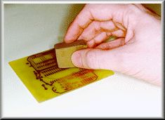 |
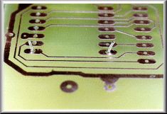
Boards must be clean to begin with, especially if they're not previously "tinned" with solder. Clean the copper tracks using e.g. an abrasive rubber block. |
|
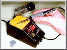 |
Clean the iron "bit" (tip) using a damp sponge. The iron featured here is an Ungar Concept 2100 Soldering Station. | |
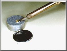 |
A useful product is Multicore's Tip Tinner Cleaner (TTC) - a 15 gramme tin of special paste which cleans and "tins" the iron, in one go. | |
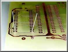 |
Insert the components and splay the leads so that the part is held in place. | |
 |
It's usually best to snip the wires to length prior to soldering. This helps prevent transmitting mechanical shocks to the copper foil. | |
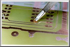 |
Apply a clean iron tip to the copper and the lead, in order to heat both items at the same time. | |
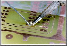 |
Continue heating and apply a few millimetres of solder. Remove the iron and allow the solder joint to cool naturally. | |
 |
It only takes a second or two, to make the perfect joint, which should be nice and shiny. Check the Guide for troubleshooting help. | |
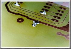 |
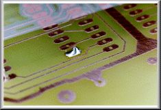
An example of a "dry" joint - the solder failed to flow, and instead beaded to form globules around the wire. | |
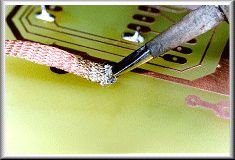 |
"Solder Wick" is a cheap and very effective way of desoldering a joint. Take care not to overheat the board. Alternatively, use a desoldering pump. | |
|
|
||
| Contacting the Author | ||
| This guide was written by Alan Winstanley, email alan@epemag.demon.co.uk | ||
|
|
||
| Copyright Notice & Disclaimer | ||
| The Basic Soldering Guide is © 1996/7/8/9 Wimborne
Publishing Limited, publishers of Everyday Practical Electronics/
ETI magazine, Wimborne, Dorset, England (http://www.epemag.wimborne.co.uk) and reproduced by
permission. The Basic Soldering Guide photographs are (c) 1999
Copyright Alan Winstanley (alan@epemag.demon.co.uk) and
reproduced by permission. You are welcome to download it, print it and distribute it for personal or educational use. It may not be used in any commercial publication, mirrored on any commercial site, nor may it be appended to or amended, or used or distributed for any commercial reason, without the prior permission of the Publishers. Every care has been taken to ensure that the information and guidance given is accurate and reliable, but since conditions of use are beyond our control, no legal liability or consequential claims will be accepted for any errors herein. The British mains voltage supply is 230V a.c. -- you should amend ratings for local conditions. |
||